Circuit Diagrams
Circuits are a means of transporting electricity to various devices and components. Throughout this book we will use circuit diagrams often so you will have to understand how to interpret them. What better way to show you how to interpret them than how to teach you how to draw them? The idea of circuit diagrams is to draw out a circuit in the simplest possible way - science is all about purpose and very little about form[i]. When we draw wires, we don’t do curves. Instead, we draw straight lines with a ruler[ii]. In between the lines we insert symbols to represent components such as bulbs. The circuit below shows a very simple circuit containing a bulb and a battery. 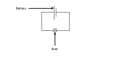 All you have to do when drawing a circuit diagram is draw all the wires and then insert the symbol for the component – a list of main components can be found in appendix two. The circuit above is described as being in series. This simply means that the electricity (current) has only one path to flow through in the circuit. The opposite of series is parallel, which is when current has multiple paths to flow through in the circuit. Below is an example of a parallel circuit containing three bulbs and a battery. 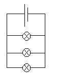 |